

This article explains the key points for designing reinforcing plates used when mounting the connector on FPCs. Understanding the key points for designing reinforcing plates will allow you to achieve stable mounting.
In another article had explained the need for FPC reinforcing plates when mounting small components, including connectors on FPCs.
So, how do you design the reinforcing plates? The points are to adopt specifications that achieve the proper hardness and thickness of reinforcing plates.
The most highly recommended material for reinforcing plates are metal, such as stainless steel, which is easy to obtain strength, or glass-reinforced epoxy or polyimide resin. When using polyimide resin plates, please pay attention to adhering foreign substances generated from fiber waste. Additionally, please take the following into consideration when designing reinforcing plates.
- Make it as thick as possible (Generally thickness of 0.2 mm or greater is recommended).
- Use an epoxy based adhesive with high adhesive strength for sticking them to FPCs.
There is also method of stacking two polyimide resin plates, which is used as an additional measure to ensure the hardness of the plates. Stacking two reinforcing plates with epoxy adhesive will allow you to achieve greater hardness than a single plate with the same thickness.
In addition, a large number of FPC pins leads to a wide FPC, which makes the FPC easier to bend, therefore making it necessary to increase the hardness of the FPC reinforcing plate.
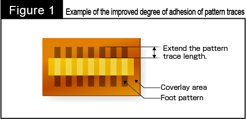
When a sufficient FPC reinforcing plate thickness cannot be secured, it is also possible to enhance the adhesion strength between the FPC and its pattern traces through a foot pattern design as measures against pattern trace delamination.
As shown in Figure 1 below, design each foot pattern trace with a length greater than the height of the coverlay opening.
Setting the pattern trace length to approximately twice the normal value can enhance the hardness of a reinforcing plate with the help of copper foil on the foot pattern.
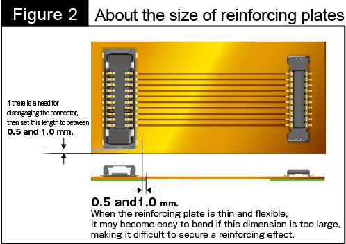
In addition, it is a basic rule to create an FPC reinforcing plate so that the plate covers and supports the back of the area on which small components including connectors are mounted.
However, please design a reinforcing plate with a length of 0.5 to 1.0 mm greater than the tip of an FPC's foot pattern to prevent stress from affecting the areas where the connector's terminals are soldered when the connector is disengaged, or the FPC is bent. (Figure 2)
How were the above explanations? This article introduced the points for the design of reinforcing plates. Please make good use it when designing them!


