Proposal for Establishing
Machinery Safety
Using Safety Relays

Leaflets Download (Free)


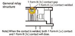
| Safety relay | General relay | |
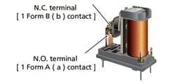
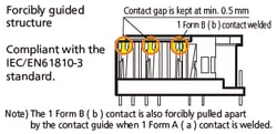
| Structure | 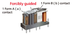 |
 |
| Features (1) |
|
The following is not guaranteed.
|
| Features (2) |
 |
 |

| Product name | SF-M | SF Slim | SF-Y | SF | SF Double contact |
| Structure |
 |
 |
 |
 |
 |
| Contact arrangement |
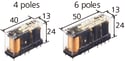
1 Form A 1 Form B | 4 poles: 2 Form A 2 Form B, 3 Form A 1 Form B 6 poles: 4 Form A 2 Form B, 5 Form A 1 Form B, 3 Form A 3 Form B |
4 poles: 2 Form A 2 Form B, 3 Form A 1 Form B 6 poles: 4 Form A 2 Form B, 5 Form A 1 Form B |
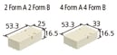
3 Form A 1 Form B | 2 Form A 2 Form B, 4 Form A 4 Form B |
| Contact rating |
N.C. : 4 A 250 V AC 30 V DC N.O. : 6 A 250 V AC 30 V DC |
6 A 250 V AC 30 V DC | 6 A 250 V AC 30 V DC | 6 A 250 V AC 30 V DC | 6 A 250 V AC 30 V DC |
| Min. switching load (reference value) |
1 mA 10 V DC | 1 mA 5 V DC | 10 mA 10 V DC | 100 mA 5 V DC | 100 mA 5 V DC |
| Rated operating power |
Operating: 270 mW Holding: 100 mW |
4 poles: 360 mW 6 poles: 500 mW |
670 mW | 500 mW | 500 mW |
| Rated coil voltage |
3, 5, 12, 16, 18, 21, 24 V DC | 12, 24, 48 V DC | 5, 12, 16, 18, 21, 24 VDC | 5, 12, 24, 48, 60 V DC | 5, 12, 24, 48, 60 V DC |
| Ambient temperature |
-40°C to +85°C | -40°C to +85°C | -40°C to +70°C | -40°C to +70°C | -40°C to +70°C |
| Safety standard |
UL/C-UL, TÜV | UL/C-UL, TÜV, Korean S, CQC | UL/C-UL, TÜV | UL/C-UL, TÜV | UL/C-UL, TÜV |
| Website | ▷ Product page ▷ Catalog Download |
▷ Product page ▷ Catalog Download |
▷ Product page ▷ Catalog Download |
▷ Product page ▷ Catalog Download |
▷ Product page ▷ Catalog Download |


Leaflets Download (Free)