In this article, we will answer customers' inquiries about load current in a solid-state relay (SSR), which is a contactless relay. As well as, mention some points to heed in circuit designing. If you are planning to use or are already using an SSR, this article will help eliminate your concerns and find solutions to your problems.
Question:
We have an SSR circuit in which the load carries a little current and is connected to an SSR. In this circuit, the load does not turn off when the primary side element turns off. Why does this happen?
Answer:
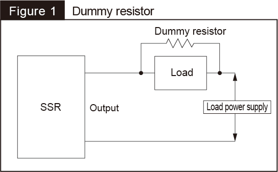
In order for the SSR to operate normally, a current flowing through the load must be equal to or larger than the "minimum load current." Check the specifications of your relay, and connect a dummy resistor in parallel to the load to make the load current equal to or larger than the "minimum load current."
The SSR has a phototriac and a triac that serve as output elements. This causes an effect in the SSR that, in some cases, results in output side element not turning off when a load current is too small. To deal with this problem, a resistor (dummy resistor is connected in parallel to the load to allow the load to carry a current flow equal to or larger than the minimum load current specified for the SSR. In this way, the load current in the SSR is kept equal to or larger than the minimum load current (see Fig. 1).

Question:
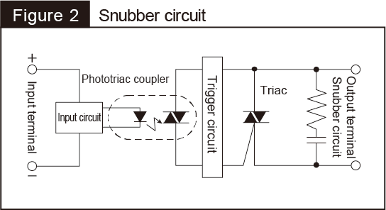
We have an SSR circuit which has a built-in snubber circuit. In this circuit, the load turns on in some cases despite the input side element having turned off. What is the cause of this behavior?
Answer:
This happens because the rated current of the load is smaller than an open-circuit leak current that flows through the snubber circuit. You need to ensure that the load current is equal to or larger than the open-circuit leak current. Connecting a dummy resistor in parallel to the load will work.

You should note, however, that such a case does not necessarily mean your SSR is defective. Sometimes the SSR behaves as if it has a problem with resetting because of impedance differences and load types. You can handle this problem by connecting a dummy resistor in parallel to the load. This reduces the voltage remaining at the load, thus allowing you to avoid a resetting failure (see Fig. 1).
The SSR we have discussed in this article is a contactless relay, which is different in structure from a PhotoMOS relay that is also classified as a contactless relay. We hope what has been described here will be helpful to you when you use an SSR.
Keywords
- SSR: SSR stands for a solid-state relay. The SSR is one of the various contactless semiconductor relays. It has a light-emitting semiconductor element, such as an LED, on the input side, and a semiconductor control element, such as transistor and triac, on the output side. These elements allow the SSR to have high-speed responses.
- Triac: A triac, which is also called a bidirectional thyristor, is made by connecting two thyristors reversely in parallel with each other. The triac constructed in this manner lets current flow both in a forward and backward direction.
- Snubber circuit: A snubber circuit is incorporated in an electronic circuit to suppress a sharp voltage increase. It prevents the destruction of a transistor, control device, etc., caused by such a voltage spike.


