

This article explains jitter and skews, which are basic terms indicating time-axis transmission characteristics, by using actual eye patterns of transmission signals.
While the previous article explained terms indicating frequency transmission characteristics, this article explains terms indicating time-axis transmission characteristics.
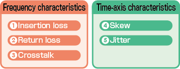
Terms (4) and (5) of the time-axis characteristics will be explained in this article.
These characteristics are also used to determine whether signals are properly transmitted.
(4) Skew
A skew indicates a transmission delay time lag between signals in a pair when they are differentially transmitted.
When signals are transmitted with a time lag between them as shown in Fig. 1 below, that is an occurrence of a skew.
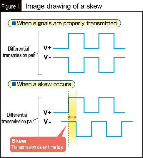
Such time lags will cause errors during data transmission.
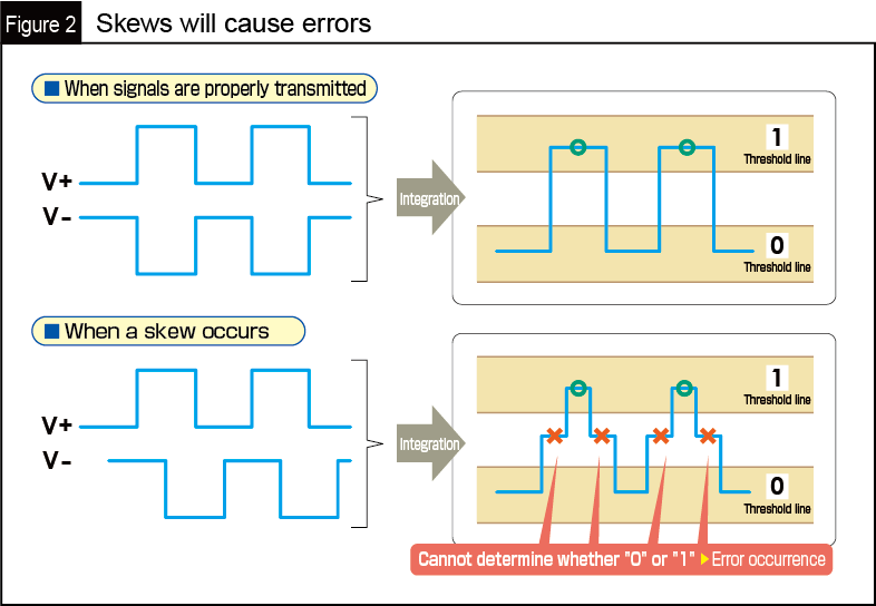
When differentially transmitted pair signals with skews are integrated into a single-ended signal, the voltage of the integrated transmission signal is partially lowered in comparison to a proper transmission without skews.
When digital signals are transmitted, data signal transmission is completed through the proper determination of data "0" or "1" by reading the voltage of signals. Therefore, the presence of signal points whose voltage is lower than it should be as shown above does not allow proper data determination.
(5) Jitter
Jitter is defined as the fluctuations of transmitted signals along the time axis.
Although it is difficult to give you a clear image of jitter by expressing it in words, viewing actual data makes it easy to understand jitter.
Please look at the following figure first.
This is called an eye pattern, which is created by superimposing every single bit of the digital transmission signals.
In the figure, the section between the two red arrows is defined as jitter. In other words, it is the horizontal width of displacements in superimposed waveforms.
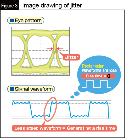
In digital signal transmission, it is ideal to precisely transmit the voltage levels of digital signals that can be clearly determined as "0" or "1" through accurate rectangular waveforms.
However, it is practically impossible to transmit such accurate waveforms, resulting in less steep waveforms.
A less steep waveform means, more specifically, that it takes more time for the voltage to change from "0" to "1."
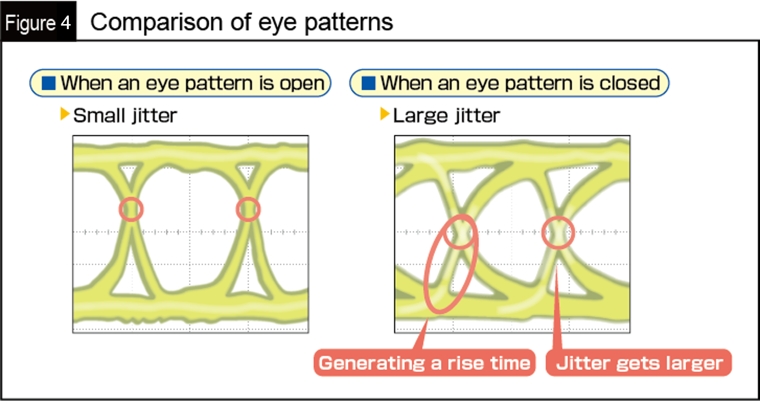
The time required for the change is referred to as a rise time.
The fluctuation of the rise time is jitter.
When the jitter gets larger, the opening of the eye pattern becomes closed as shown in Fig. 4.
When the eye pattern becomes closed like this, it is difficult to decide whether the voltage levels of the signals are "0" or "1."
Panasonic provides these data in response to customer demand. Please feel free to contact us from here.
How were the above explanations? This article explained time-axis characteristics as part of transmission characteristics essential for evaluating the performance of signal transmission. In addition to the previous article, provided information for you to understand the basic terms of transmission characteristics. Please make effective use of the information when designing your products.


