

In this articlee, we will explain some basic knowledge you need in order to read an eye pattern correctly. Reading an eye pattern correctly is essential in transmission path designing. What you'll learn from this article will be a great help in your design work.
We assume that anybody who engages in design work has seen an eye pattern somewhere. Using the eye pattern, you can visually check the waveform of transmission data and its skewing, jittering, etc. In other words, the eye pattern gives you a visual check procedure that determines whether data is transmitted correctly.
Segments of a transmission signal, with each segment corresponding to 1 bit, are superposed together to create the eye pattern (see Fig. 1).

The eye pattern has three important factors as listed below.
- Extent of the opening of an eye-shaped part ((5) and (6))
- Rising time ((3) and (4))
- Jitter ((7))
* (3) to (7) indicated in parentheses are described in Fig. 1.
Whether transmission characteristics are fine or not can be determined by checking the extent of the opening of an eye-shaped part (opening in a central part of the eye pattern).
Wide opened eye-shaped part ⇒ fine transmission characteristics
Narrow eye-shaped part ⇒ inferior transmission characteristics
In short, an eye pattern with wide opened eye-shaped parts indicates a state of proper signal transmission.
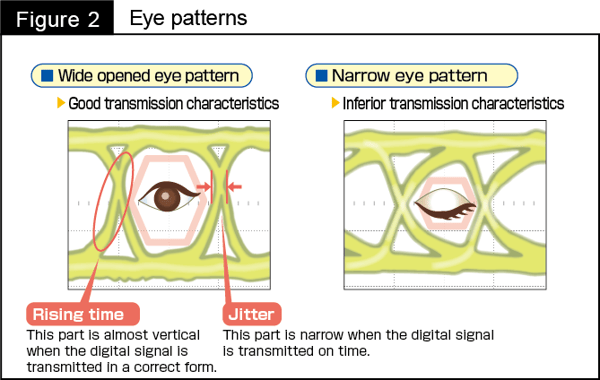
A rising time refers to a time the signal voltage takes to change from "0" to "1."
Jitter means fluctuations in the rising time.
A change in the waveform of the transmission signal results in a change in the rising time. In such a case, jittering intensifies, narrowing the eye-shaped parts of the eye pattern.Narrower eye-shaped parts make it difficult to correctly read voltage values of "0" and "1", in which case an error may occur.
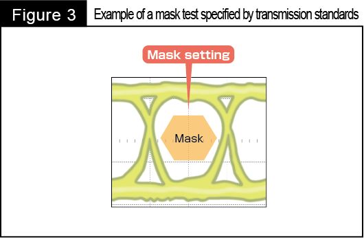
Some transmission standards require the eye pattern to pass a mask test.
To pass this mask test, as shown in Fig. 3 below, the transmission signal waveform must be configured to avoid overlapping a mask area specified by the standards.
Panasonic provides customers with eye patterns for connectors according to the customers' needs. Please feel free to contact us on this matter.
We have discussed the eye pattern in this article. What you've learned is basic but is an important step to take in understanding the eye pattern – data that is essential in transmission signal evaluation. I hope this article will be a great help in your design work.


