

This article explains temperature profile for connector reflow mounting, based on questions from customers. Confirming temperature profile is key to prevent soldering defects. By all means, please make use of the information in this article for your reference.
As you are aware, the reflow mounting method is frequently used for small connectors. Through using catalogs, etc. connector manufacturers inform users with temperature profile information for using connector reflow mounting. We ask you to confirm such information prior to reflow mounting.
Such temperature profile can be divided into four stages depending on the temperature settings. Figure 1 shows the reflow temperature profile recommended by Panasonic. The following explains points to note in each stages.
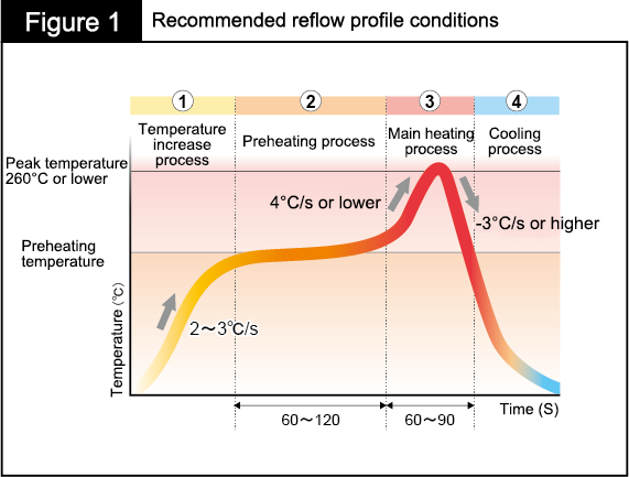
(1) Temperature rising process
This is a process step in which the reflow temperature is raised while evaporating solvent contained in solder flux.
Note: Be sure not to suddenly rise the temperature. A sudden temperature raise causes solvent to boil, resulting in the generation of solder balls (*1) and voids (*2).
(2) Preheating process
This is a process step for standardizing the temperatures of parts to prevent variations as well as setting conditions to facilitate the activation of flux.
Note: A preheating process that is too short tends to generate the following defects.
Defect examples) wicking phenomenon (*3), solder bridge (*4), poor solder wettability
Also, if the preheating process continued for two minutes or longer depletes the activator before the main heating process starts, thereby tending to generate solder balls.
(3) Main heating process
This is a process step for uniformly increasing the temperatures of the PC board and mounted parts for promoting the activation state of flux to increase the temperature to the solder melting temperature.
Note: Be sure not to rise increase the temperature suddenly. A sudden temperature increase causes voids.
On the other hand, a temperature increase speed that is too slow results in poor solder wettability.
Be sure not to maintain a high temperature for a long time. A high reflow temperature maintained for a long time induces the melting and thermal deformation of resin used in mounted parts.
(4) Cooling process
A process step for cooling mounted parts using an air blast.
Note: Be sure to reduce the temperature quickly. Slow cooling may result in weak solder strength.
*Note
1) Solder ball: Ball-shaped lumps on solder. Such balls may spatter to other contact areas, causing short-circuits.
2) Void generation: Voids are generated inside solder. Voids weaken solder strength.
3) Wicking phenomenon: Phenomenon in which solder moves up to connector terminals. A wicking phenomenon results in impaired solder strength and conduction failures.
4) Solder bridge: Soldering adjacent terminals
How were the explanations above? This article has explained temperature profile in the reflow mounting of connecter.
Please understand the detailed points to note and by all means make good use of such information to prevent solder defects.


