Technical terms related to operation switches
1.Rating
The ratings of an operation switch are generally referred to as criteria values to ensure the characteristics and performance of the switch under specific conditions. Such examples include the rated voltage and rated current.
2.Electrical life
Electrical life refers to the lifetime of a switch when it is switched with its contacts connected to the rated load under the prescribed conditions.
3.Mechanical life
The mechanical life of a switch refers to the lifetime of a switch when it is operated at the prescribed operating frequency while its contacts are not energized.
4.Dielectric Withstand voltage
The withstand voltage refers to the maximum threshold voltage up to which no insulation breakdown occurs when high voltages are applied to the specified measurement sections of a switch for one minute.
5.Insulation resistance
The insulation resistance refers to the resistance value at the same measurement sections as the withstand voltage.
6.Contact resistance
The contact resistance of a switch indicates the electrical resistance of the section where the switch's contacts come in contact with each other. In general, it refers to the resistance value including the conductor resistance of the spring and terminal sections.
7.Vibration resistance
The vibration resistance of a switch refers to the resistance to vibrations during use, which is defined as the maximum vibration within which its closed contacts do not open for more than the specified period.
8.Shock resistance
The shock resistance of a switch refers to the resistance to shock during use and defined as the maximum shock within which the switch's closed contacts do not open for more than the specified period.
9.Allowable frequency of operation
The allowable frequency of operation refers to the maximum operating frequency at which a switch can be operated while sustaining its mechanical life (or electrical life).
10.Temperature rise value
The temperature rise of a switch indicates the maximum temperature rise due to heat generated at its terminals when the rated current flows through the contacts.
11.Actuator strength
When static loads are applied to the switch handle in the operation direction for the specified period, the handle strength refers to the maximum load up to which the switch operates without any loss of function.
12.Terminal strength
When static loads are applied to the terminal of a switch (in all directions unless otherwise specified) for the specified period, the terminal strength refers to the maximum load up to which the switch operates without any loss of function (except for the deformation of the terminal).
Types of loads
1.Resistive load
A resistive load consists of a resistance component only with a power factor of 1 (cos φ = 1). The rating of a switch indicates the current capacity for use in AC.
2.DC load
When switching DC loads, the direction of the current is constant, unlike when switching AC loads, resulting in an arc with a longer duration than is the case for AC under the same applied voltage.
3.Incandescent lamp load
When a lamp is lit by turning the switch ON, an inrush current of 10 to 15 times the stationary current flows instantaneously. Since this may fuse the contacts of the switch, please select a switch by considering this transient current.
4.Induction load
When switching inductive loads (relays, solenoids, buzzers, etc.), a reverse voltage may generate an arc and cause contact faults. Therefore, it is recommended to insert a proper spark quenching circuit (see the figure below) into the switch circuit.
| Circuit diagram and precautions for use of spark quenching circuits |
|
(1) The resistance r must be several tens of ohms. |
|
The circuit can be used for AC and DC applications. |
|
(1) Exclusive for DC applications |
|
The circuit can be used for AC and DC applications. |
5.Motor load
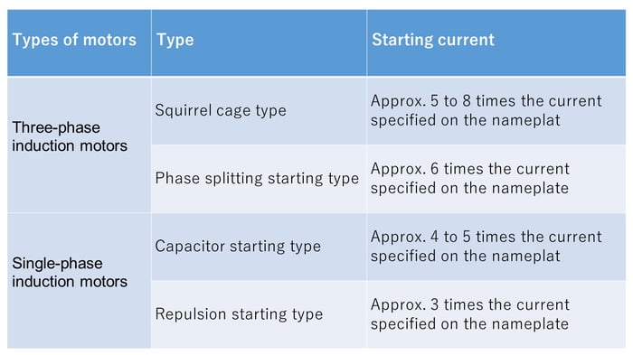
When a motor is started, a starting current of 3 to 8 times the stationary current flows, which may fuse the contacts. The starting currents that flow in motors differ depending on the types of motors; however, they are several times the respective nominal currents. Therefore, please select a switch by referring to the values shown in the table below. Note that when rotating a motor in the reverse direction, it is necessary to prevent the combined starting and reverse currents to flow by using an ON-OFF-ON type switch.

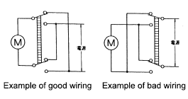
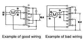
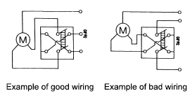
While such a motor is rotating, if it is switched to rotate in the reverse direction, then a current equivalent to approx. twice the starting current flows. When a switch is used for a load that causes a transient phenomenon due to motor reverse rotation, heteropolar switching, or other operations, a time lag during switching may cause an arc short circuit between the different types of poles. Please pay full attention to this risk when using a switch for such applications.
|
Example of a circuit for rotating a unipolar motor in the reverse direction
|
|
Example of a circuit for switching between the high-output and low-output mode of a single-phase induction motor (capacitor)
|
|
Example of a circuit for rotating a three-phase motor in the reverse direction
|
6.Capacitor load
When a switch is used for capacitive loads, including mercury lamps, fluorescent lights, and capacitive circuits, a very high inrush current flows when the switch is turned ON. Therefore, please measure the transient current value through the actual load and use a switch with an operating current range below the rated current or use the switch after verifying its proper operation when used for switching the actual load.
Snap-action switches terminology
1.Snap-action switches
A snap-action switches is a compact switch (hereinafter referred to as a "switch") that has contacts separated by a very small gap, and a snap-action mechanism, wherein a contact mechanism opened and closed by the specified movements and forces is covered by a case, with an actuator installed on the outside.
2.Actuator
An actuator, which is part of the switch, conveys the external force applied to the switch to the internal spring mechanism to move the movable contact to turn the switch on and off.
3.Actuator limiter
An actuator limiter is the section of a switch for limiting the actuator's movement in the switch operation direction.
4.Rated values
The rated values are referred to as criteria values to ensure the characteristics and performance of snap-action switches. For example, they include the rated current and rated voltage of snap-action switches under specific preconditions (types of loads, current, voltage, switching frequencies, etc.).
5.Mechanical life
The mechanical life of a switch refers to the lifetime of a switch when it is operated at the prescribed operating frequency while its contacts are not energized. (Mechanical life testing is normally carried out by using a cam for opening and closing operations at a frequency of 60 times/min. and operation speed of 100 mm/sec.)
6.Electrical life
The electrical life refers to the lifetime of a switch when it is switched with its contacts connected to the rated load. (Electrical life testing is normally carried out by using a cam for opening and closing operations at a frequency of 20 times/min. and operation speed of 100 mm/sec.)
7.Contact arrangement
The contact arrangement of a switch refers to the electrical input and output circuit configurations of its contacts in accordance with a variety of applications.
|
Switching type |
 |
|
Normally closed type |
 |
|
Normally open type |
 |
*Terminal symbol
COM: Common terminal NC: Normally closed terminal NO: Normally open terminal
8.Insulation resistance
The insulation resistance of a switch is defined as the resistance values between separated terminals and between each terminal and non-charged metal sections or grounding terminals.
9.Withstand voltage
The withstand voltage refers to the maximum threshold voltage up to which no insulation breakdown occurs when high voltages are applied to the specified measurement sections of a switch for one minute.
10.Contact resistance
The contact resistance of a switch indicates the electrical resistance of the section where the switch's contacts come in contact with each other. In general, it refers to the resistance value including the conductor resistance of the spring and terminal sections.
11.Vibration resistance
Malfunction vibration: Refers to the resistance to vibrations during the use of a snap-action switches and defined as the maximum vibration within which the switch's closed contacts do not open for more than the specified period.
12.Shock resistance
Durability shock: Refers to the resistance to mechanical shock during the transportation or mounting of a snap-action switches and defined as the maximum shock that does not damage each section of the switch and which satisfies the required operation characteristics.
Malfunction shock: Refers to the resistance to shock during the use of a snap-action switches and defined as the maximum shock within which the switch's closed contacts do not open for more than the specified period.


