

This article explains how to protect a circuit from a surge - a troublesome phenomenon that can lead to the destruction of a circuit element.
We have questions from customers on how to protect relay coils from surges, which we will answer by providing detailed explanations. A "surge" refers to the generation of an extremely high voltage that far exceeds a voltage generated in a steady state. It is a troublesome phenomenon that can lead to the destruction of a circuit element. What should you do to protect your circuit from a surge, i.e., a surge voltage? We will now tell you about the method you should take to protect the circuit.
|
Question: What should I do to protect a contact or circuit from a surge voltage that is generated when the power supply to an inductive load is cut off? Answer: A relay coil is an inductive load. This inductive load in a circuit generates a large surge voltage when it is cut off from the circuit, and this surge voltage can destroy contacts or electronic circuit elements. Measures for dealing with such surge voltages vary depending on whether the circuit carries AC or DC. A diode works well in a DC circuit, while a CR circuit is effective in an AC circuit. These diodes and CR circuits must be connected in parallel with the load. |
Let us explain surge voltages in greater detail. When an inductive load, such as a relay coil, is cut off from a circuit, the load generates a high voltage of hundreds to thousands of volts in the reverse direction to the source voltage. This voltage is referred to as "reverse voltage." A high reverse voltage causes a large current to flow through the circuit, which damages the contact that controls power supply to the inductive load, and the circuit itself as well. As a result, the service life of the circuit is reduced significantly.
To protect the contact and circuit from this reverse voltage, you need a protective circuit. A protective circuit for a DC inductive load is different from that for an AC inductive load. We will now describe the respective measures to take for these DC and AC inductive loads.
1.In the case of a DC inductive load
As shown in Fig. 1, a diode works well as a protective circuit for a DC inductive load.
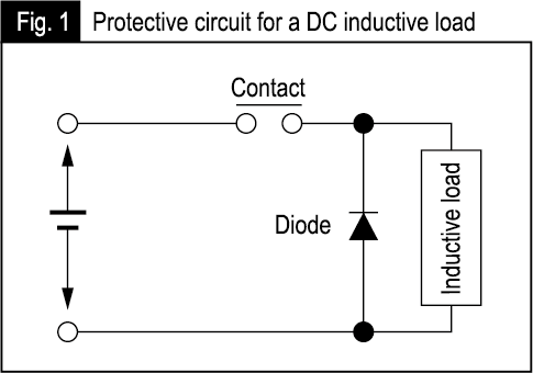
This protective circuit can only be applied to the DC circuit. The diode, which is a type of load, consumes an incoming surge current, thus protecting the circuit and its element. For a stable electronic circuit whose circuit voltage is not very high, you have to select a diode with a reverse withstand voltage of 2 to 3 times the source voltage. For an ordinary circuit, we recommend that you select a diode having a reverse withstand voltage of 10 times or more the circuit voltage. Make sure that the diode carries a forward current equal to or larger than a load current. We offer a lineup of relays for control panels, from which you can choose a relay with a built-in diode.
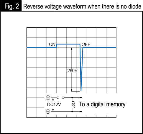
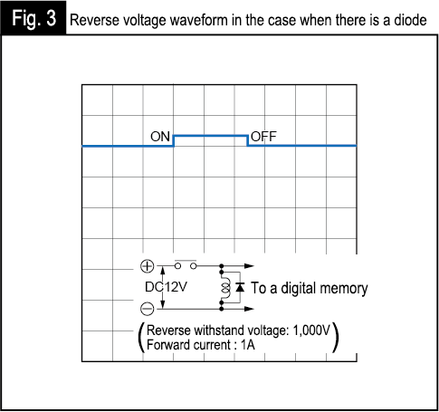
We will now compare a reverse voltage generated by a DC inductive load when a diode is present with one when there is no diode by referring to the following diagrams. Fig. 2 shows a reverse voltage waveform in the case when there is no diode, and Fig. 3 when there is a diode. In the case when there is no diode, as shown in Fig. 2, a reverse voltage of 260 V is generated when the DC inductive load is cut off from the circuit. In contrast, when there is a diode, no reverse voltage is generated because any surge current is consumed by the diode, as shown in Fig. 3.
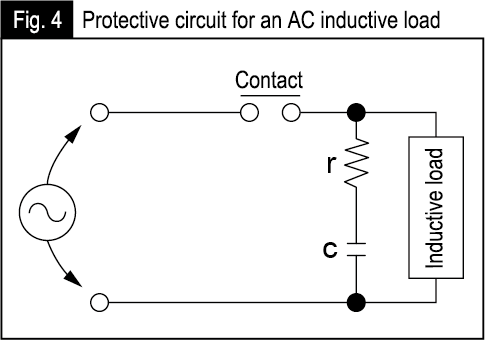
2.In the case of an AC inductive load
When an AC inductive load is cut off from a circuit, a reverse voltage is generated at both ends of the AC inductive load. In this case, the CR circuit shown in Fig. 4 works effectively as a circuit protector.
The CR circuit lets its capacitor absorb the surge created by opening the contact, thereby protecting the circuit and its element. In Fig. 4, a capacitor c has a function of controlling the discharge caused by the opening of the contact, and a resistor r is provided to limit the inrush current from the capacitor c when the contact is closed.
Here are standard specifications of capacitor c and resistor r.
- Capacitor c: 0.5 to 1 (μF) for contact current 1 A
- Resistance r: 0.5 to 1 (Ω) for contact voltage 1 V
These are not always the proper values to adopt and may vary depending on the features and characteristics of the load. You have to use a capacitor c for AC circuits that have a withstand voltage ranging from 200 to 300 V.
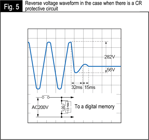
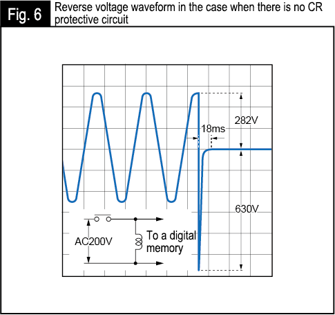
The reverse voltage waveforms generated by the AC inductive load in the case when there is a CR circuit and when there is no CR circuit are shown respectively in Figs. 5 and 6. Fig. 5, which represents the case when there is a CR circuit, shows that when the contact is opened, the circuit is turned OFF without generating a surge voltage higher than the source voltage. In contrast, Fig. 6, which is the case when there is no CR circuit, shows that a surge voltage of 630 V, which is about 3 times the source voltage of 200 V AC, is generated in a timespan of 18 ms following the opening of the contact.
You can also use the CR protective circuit in a DC circuit. In this case, the capacitor for DC circuits to be used.
Just explained functions for protecting relays from surges. Hoping that you understood the case where a surge voltage is generated in a circuit with no protective circuit and where a surge voltage is not generated in a circuit with a protective circuit. A surge voltage is generated when the contact is opened. We recommend that you protect the contact and circuit by implementing surge-prevention measures applicable to AC and DC inductive loads respectively.
However, please be careful when implementing surge-prevention measures. Simply connecting a diode or capacitor to the circuit will not suffice. For example, placing a capacitor between contacts may lead to a case where when the contacts are closed, charges accumulated in the capacitor are released to create a short current, which damages the circuit and its element. Your surge-prevention measures must be adjusted to the circuit configuration.
Keywords
- Surge: A surge refers to a high voltage that is generated instantaneously when an inductive load is cut off from the circuit.
- Reverse withstand voltage: A reverse withstand voltage refers to the maximum voltage that is in the reverse direction of the forward voltage of a diode and at which the diode still maintains its insulation property.


